-
Upgrade Options
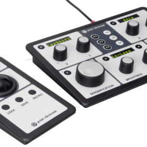
Control panels
Manufacturer: PTE
Product condition:
Vintage:Price: click here for enquiry
-
Upgrade Options
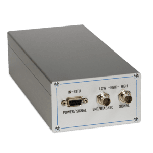
EA amplifiers / Lock-in EA amplifier
Manufacturer: PTE
Product condition:
Vintage:Price: click here for enquiry
-
Upgrade Options
EDS detector
Manufacturer: PTE
Product condition:
Vintage:Price: click here for enquiry
-
Upgrade Options
HT BSE detector
Manufacturer: PTE
Product condition:
Vintage:Price: click here for enquiry
-
Upgrade Options
microCal
Manufacturer: PTE
Product condition:
Vintage:Price: click here for enquiry
-
Upgrade Options
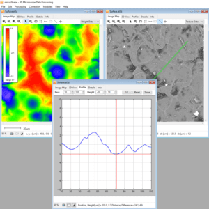
microShape
Manufacturer: PTE
Product condition:
Vintage:Price: click here for enquiry
-
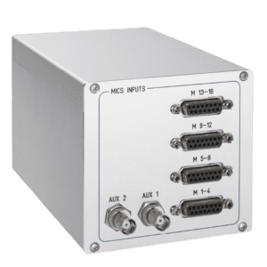
SEM Upgrades
MICS-4/8/12/16 signal amplifier
Manufacturer: PTE
Product condition:
Vintage:Price: click here for enquiry
-
Upgrade Options
Premium BSE detector
Manufacturer: PTE
Product condition:
Vintage:Price: click here for enquiry