Showing all 8 results

  • Upgrade Options

    Control panels

    Control panels
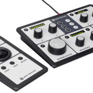
    * For increased speed and productivity of experienced users
    * SEM panel with magnification, focus, image shift, brighness, contrast, stigmatism, etc.
    * Stage panel with trackball or joystick, XYRZ locks and store/recall functions
    * USB2 controlled and fully integrated wth the microscope control software

  • Upgrade Options

    EA amplifiers / Lock-in EA amplifier

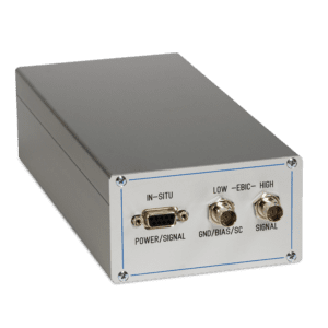
    EA amplifiers are complex multi-stage amplification systems with integrated current & voltage sources for Electrical Analysis. All versions feature a high-speed transimpedance preamplifier for imaging, a bandwidth filter and a flexible second-stage amplifier for imaging. High-precision voltage and current sources are integrated into the compact housing, as required for biasing, IV sweeps and compensation. Packaging is miniaturised in order to reduce cable lengths, increase speed and optimise signal-to-noise ratio.

    Standard features
    * High-speed and low-noise ex-situ preamplifier with adjustable gain
    * Automatic routing, to ground, bias or beam current meter
    * Lowpass filter to match amplification with imaging speed
    * Second-stage amplifier for fine image adjustments
    * Voltage source for device biasing
    * Current source to compensate for forward or reverse signals
    * Auto-zero function for calibration

    Optional features
    * In-situ preamplifier for low impedance samples (with the Premium EA sample holder)
    * Automatic current – voltage sweeps for device characterisation

    The amplifer is part of the EA for SEM system and is designed for a wide range of Electrical Analysis techniques.

    Versions
    1. EA amplifier
    * ex-situ preamplifier for junctions and Schottky barriers
    * fully calibrated electronics for quantitative technique

    2. Lock-in EA amplifier
    * integrated clock generator for beam blanker
    * ex-situ preamplifier for junctions and Schottky barriers
    * analog lock-in amplification with de-modulation

    Control
    * USB2 hardware interface
    * device driver for Microsoft Windows
    * independent control library
    * integrated DISS control panel

    Inputs
    * HIGH input for sample signal
    * LOW input for sample gound
    * DC input power (back panel)
    * GND input (case)

    Outputs
    * Amplified output for imaging (back panel)
    * LOW output for bias voltage
    * BC output for external beam current measurement
    * EBAC output for in-situ electronics

    Ex-situ preamplifier
    * 20,000 Ohm minimum sample resistance
    * 10^3 … 10^10 V/A configurable gain
    * 8 µs minimum pixed dwell time, depending on sample impedance
    * 12-bit ADC for live signal inspection

    In-situ preamplifier (optional)
    * 1,000 Ohm minimum recommended sample resistance
    * 10ˆ7 V/A fixed transimpedanced gain
    * 16 µs minimum pixed dwell time, depending on sample impedance

    Second-stage amplifier
    * -1 … 1 µA, 16-bit input offset (brightness)
    * 0.1 … 100x, 16-bit gain (contrast)
    * 0.5 MHz at 10^9 V/A bandwidth
    * 8-levels low-pass filter
    * manual signal inversion

    Integrated sources
    * -10 … 10 V, 16-bit voltage bias
    * -10 … 10 µA, 16-bit current compensation
    * 100 pA internal source for calibration

  • Upgrade Options

    EDS detector

    EDS detector
    * QUANTAX Compact system by Bruker, containing XFlash® 730M silicon drift detector (SDD), an electronic module, and ESPRIT Compact software
    * Allows line scanning and spectral element mapping
    * Qualitative and quantitative material analyses
    * Fast analysis and reporting

  • Upgrade Options

    HT BSE detector

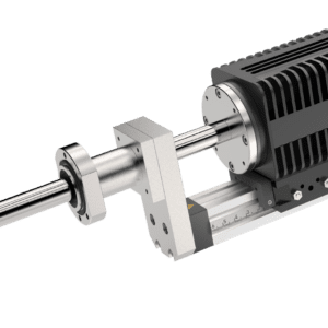
    Electrode-based detectors are specially designed for in-situ High Temperature experiments where conventional detectors cannot be used. This is, because light and thermal electrons emitted by the hot sample easily saturate the electronics, and because the unavoidable contamination from the in-situ conditions limits the lifetime of delicate sensors.

    In this new design, BackScattered Electrons (BSE) are absorbed in robust electrodes (metal plates) placed at the detection plane, the resultant absorbed current is preamplifier in-situ, and then amplified and mixed further ex-situ. Secondary and thermal electrons are repelled away, as a bias voltage is applied to the electrodes through the detector galvanic isolation. Light, either emitted from the hot sample, or scattered from a laser heater, does not produce signal in such technology, the detector is inherently light-blind.

    Electrodes can be coated in various materials to optimise absorption efficiency at particular energy ranges, e.g. Carbon coating for higher acceleration voltages, and can be easily disassembled, cleaned and recoated.

    Of course, four quadrant electrodes are used to enable 3D surface analysis when combined with our calibrated SEM scan controller (DISS6) and Topographic reconstruction software.

    Quadrant electrodes
    * Four metal electrodes with carbon coating
    * Each electrode with own in-situ preamplifier
    * Adjustable bias voltage applied to all
    * Size and geometry adapted to SEM model

    Easy to clean
    * Entire detector front end is easily removed
    * Electrodes can be cleaned and recoated as needed
    * Screws are used for easy on-site disassembly
    * Various electrode coatings may be reapplied

    High Temperature
    * Electrodes are blind to light emitted by hot samples
    * Thermal electrons are filtered using the detector bias
    * Maximum temperature limited only by radiative heating
    * Compatible with laser heating

    Quantitative measurements
    * Electronic gains, offsets and bias are factory calibrated
    * Amplification is temperature stabilized
    * Current collected into sensing electrodes is measured
    (when combined with calibrated Scan controller for SEM (DISS6) and COMPO calibration sample)

    Surface analysis
    * TOPO and COMPO mix is done in the detector hardware
    * 4Q signals are designed for topographic reconstruction
    * Surface height/topography is measured
    (when combined with Scan controller for SEM (DISS6) and TOPO calibration sample)

    SPECIFICATIONS:

    Sensors
    * 4x quadrant electrodes Carbon coated
    * typ. 5 mm inner diameter typ. 25 mm outer diameter
    * -10…10 V voltage bias

    Preamplifiers
    * 4x mounted in-situ
    * Galvanic isolation
    * 5×10⁷ V/A
    * 50 kHz bandwidth

    Main amplifier (MICS-4)
    * 4x independent signal channels
    * -1.25 … 1.25 V (-50…50 mV with attenuator) input offset
    * 1x … 1,800x gain
    * -1.25 … 1.25 V output offset
    * 3.4 MHz…34 Hz low-pass filter
    * Automated 4Q global brightness and contrast
    * Automated input offsets (dark correction)
    * Automated gain normalization (bright correction)
    * COMPO hardware mix signal (sum of BSE1…BSE4)
    * TOPO hardware mixed signal (mix of BSE1…BSE4)

    Mechanics (LIMA)
    * Port mounted, with vacuum bellows
    * Motorized insertion/retraction motion
    * -4…4 mm manual lateral and height alignment
    * 10 µm repositioning step size
    * Integrated touch alarm, with automatic stop and retraction
    * Passive cooling

    Interfaces
    * 1x USB 2.0 for amplifier control
    * 1x USB 2.0 for motion control
    * 1x RJ45 signal outputs

    Signal Outputs
    * Independent BSE1…BSE4
    * COMPO (sum of BSE1…BSE4)
    * TOPO (mix of BSE1…BSE4)

    Software – Control
    * Detector drawing with selectable quadrants
    * Bias, brightness and contrast controls
    * Individual quadrants, or grouped COMPO/TOPO control
    * Automatic go to inserted/retracted positions
    * Fine repositioning/adjustments in mm units
    * Windows 11 … Windows 7

    Software – In-situ Automation
    * XML file format open/save settings
    * JSON/RPC interface for remote control
    * Automated brightness and contrast

  • SEM Upgrades

    MICS-4/8/12/16 signal amplifier

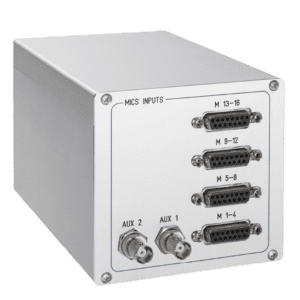
    Multi Channel Signal (MICS) amplifiers are advanced amplifiers for industrial and research instrumentation. Main features include simultaneous amplification of multiple analog signals, calibrated gains and offsets, live signal mixing and automatic control functions. A range of auxiliary features are included for ease of integration with solid-state detectors, including supply of power and biasing voltage. MICS amplifiers are available in various configurations of four sets of differential inputs/outputs, as well as two auxiliary inputs for external signals. Control of all settings is made over standard USB 2.0 interface, including dedicated DLL library and control app for Microsoft Windows.

    All stages of amplification are calibrated in factory, as required for a range of quantitative techniques.

    Independent channels
    * 2…3600 x gain for high Impedance sink
    * 1…1800 x gain for 50 Ohm termination
    * -1.25 … 1.25 V input and output offsets
    * 1/100 optional attenuator for fine control
    * 8-level lowpass filter
    Auto brightness and contrast
    * adjustable measurement time
    * configurable lowpass constant
    * tolerance and peak settings
    Global brightness and contrast
    * auto dark-level correction
    * auto gain normalisation correction
    * hardware average output
    * hardware mixed outpot, configurable signal polarities
    Power and bias supply
    * -3 … 3 V integrated detector power supply
    * 60 V switcheable bias
    Control
    * USB2 hardware interface
    * PEUSB driver for Microsoft Windows
    * stand-alone control application
    * integrated DISS control panel

  • SEM Upgrades

    New electronics for the complete SEM

    The Upgrade Kit provides your SEM with new cutting-edge electronics and software, including new power supplies for lenses and scanning coils, new controllers for vacuum, high-voltage and stage, new amplifiers for electron detectors, and new scan generator for image acquisition.

    Every microscope configuration and install is carefully tailored for each customer.

    The upgrade kits consist of hardware, software and selectable options.

  • Upgrade Options

    Premium BSE detector

    Premium BSE detector is our highest performance Si-based detector for materials science, geology and industrial applications.

    A four-quadrant sensor geometry is used, coupled with four independent in-situ preamplifiers, to give full flexibility for the traditional COMPO and TOPO modes, or the new calibrated 3D measurement mode with topographic reconstruction.

    A motorised insertion/retraction mechanism is included, with alignment table for the left/right and up/down directions, and bellows for reliable vacuum. An optional MICS-4 amplifier can be embedded into the detector, for a fully self-contained detector with quantitative amplification, independent brightness and contrast controls, and hardware signal mixing.

    Premium BSE sensor
    * detector-grade Si chip
    * four-quadrant (4Q) geometry
    * * chip on ceramic board mount
    * 6 mm inner diameter
    * 20 mm outer diameter
    * 1 kV minimum acceleration voltage

    In-situ preamplifier
    * in situ mount
    * 105 V/A gain
    * 200 ns minimum dwell time (gain dependent)

    Mechanics (LIMA)
    * Port mounted, with vacuum bellows
    * Motorized insertion/retraction motion
    * -4…4 mm manual lateral and height alignment
    * 10 µm repositioning step size
    * Integrated touch alarm, with automatic stop and retraction
    * Passive cooling

    Main amplifier (MICS-4) (optional)
    * 4x independent signal channels
    * -1.25 … 1.25 V (-50…50 mV with attenuator) input offset
    * 1x … 1,800x gain
    * -1.25 … 1.25 V output offset
    * 3.4 MHz…34 Hz low-pass filter
    * Automated 4Q global brightness and contrast
    * Automated input offsets (dark correction)
    * Automated gain normalization (bright correction)
    * COMPO hardware mix signal (sum of BSE1…BSE4)
    * TOPO hardware mixed signal (mix of BSE1…BSE4)

    Software – Control
    * Detector drawing with selectable quadrants
    * Bias, brightness and contrast controls
    * Individual quadrants, or grouped COMPO/TOPO control
    * Automatic go to inserted/retracted positions
    * Fine repositioning/adjustments in mm units
    * Windows 11 … Windows 7

    Software – Automation
    * XML file format open/save settings
    * JSON/RPC interface for remote control
    * Automated brightness and contrast

  • SEM Upgrades

    Stage controller

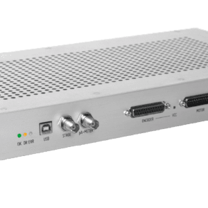
    Smart controller of motorised sample stages for SEM and SEM-FIB, up to 6 motors or steppers, including touch alarm and hardware limits, with direct joystick control or software control over USB port.

    Stage controller increases efficiency of microscope operation with

    High-speed repositioning to coordinates, screen point or saved locations, including backslash correction
    Automatic sample reorientation with rotation and displacement corrections
    Integrated touch alarm and safe zone limits, including hardware retraction on touch
    In combination with imaging systems, the stage controller enables large area techniques

    Record automatic data for image stitching over large areas.
    Acquire sparse sampled image data for statistic analysis.
    Return to acquisition position for further inspection.

    Control
    * Hardware control over trackball / joystic connector
    * Software control over USB2
    Inputs
    * max. 6 encoder inputs for positions
    * microswitch inputs for hardware limits
    * touch alarm
    Outputs
    * max. 6 DC motor or stepper outputs
    * beam current output
    * LEDs for status (OK, DR, ERR and VCC)

Shopping Cart